The History and Ingenuity of the Buffer Ring: Part 2
The History and Ingenuity of the Buffer Ring: Part II
In the 1980s, the Buffer Ring began to gain real traction in the hydraulic sealing market. Customers quickly recognized that the addition of this single component dramatically enhanced overall system performance.
While the manufacturing cost increased slightly, the trade-off was worth it: lower operating temperatures, smoother motion, quieter operation, and most notably, a significant reduction in warranty claims and field failures.
The Buffer Ring proved that a small addition to the rod gland could have an outsized impact on hydraulic cylinder efficiency and longevity.
Buffer rings can also be manufactured as piston seals, though in that configuration, two would be required to operate in both directions. In most cases, a small amount of internal leakage across a Teflon® piston seal is acceptable — since it occurs entirely within the system.
The History of the Buffer Ring
The Buffer Ring originated in Germany and was initially designed to be used with a standard O-ring energizer. But when the design was tested in the United States, engineers made an important discovery: replacing the O-ring with a square ring energizer increased the sealing load by nearly 30%, while also reducing leakage during cylinder extension.
At the time, the gland geometries for the Buffer Ring had already been standardized, so designers simply adapted the configuration — reducing the elastomer width to make room for the new square ring and PTFE sealing element.
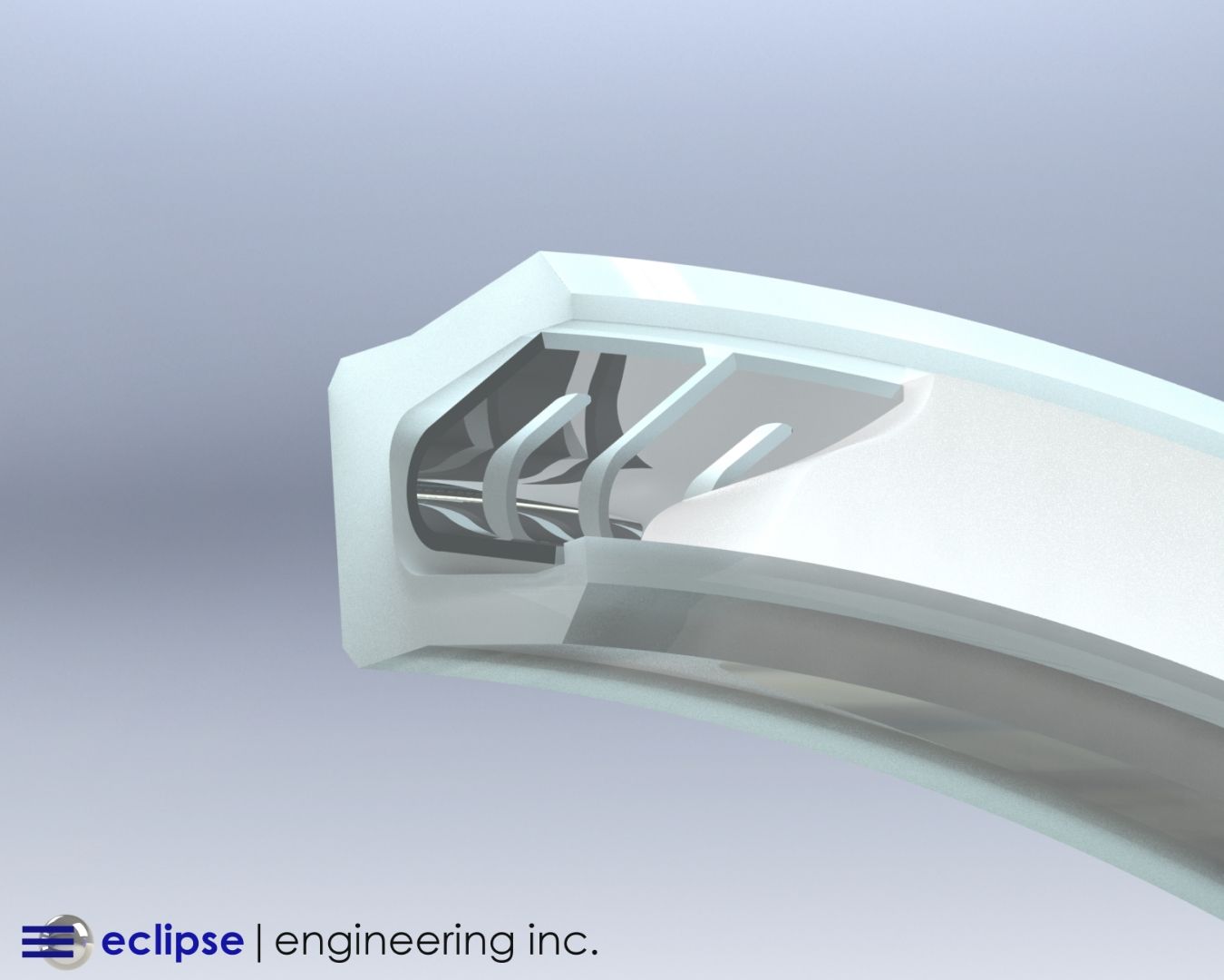
This adjustment opened the door to stacked Buffer Ring designs, where two rings could be used without the need for a traditional U-cup.
When paired with a double-acting wiper, leaked oil could be recaptured and returned into the system, creating a more self-contained and efficient hydraulic circuit.
In clean operating environments, these cylinders could even function without an external wiper — though a minor amount of leakage over time was expected.
For construction and heavy equipment applications, however, the addition of a wiper remained standard practice to keep contaminants out.
Back to the Square Ring
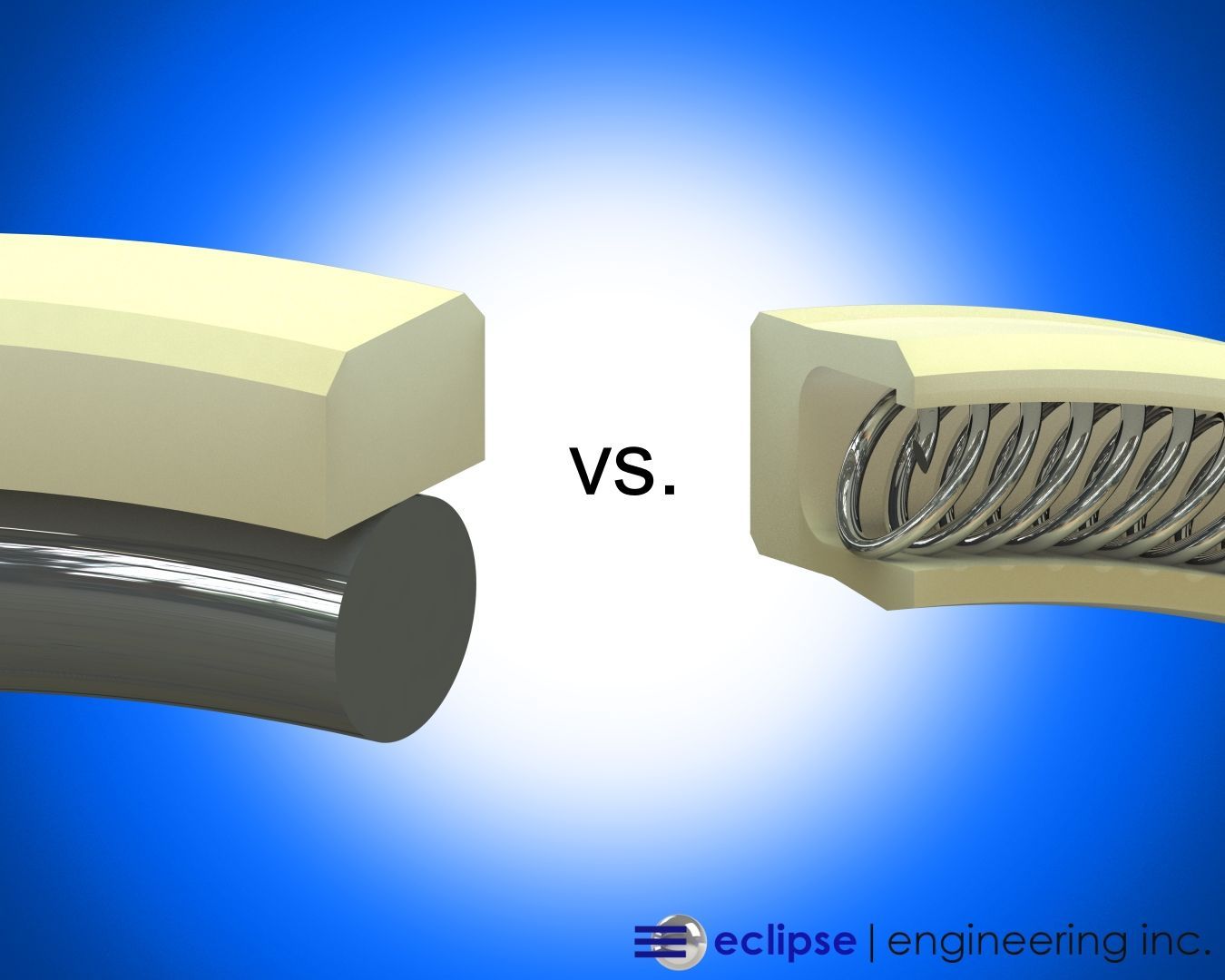
A small engineering debate emerged between German and American designers over which energizer type — O-ring or square ring — provided superior performance.
The German design had international recognition, but American engineers favored the square ring for its greater sealing load and stability. In the end, a compromise was reached: increasing the O-ring squeeze achieved better sealability without abandoning the traditional European design.
The decision wasn’t purely technical — square rings weren’t widely available in Europe, and the “not-invented-here” mentality influenced adoption. Still, both versions performed well in the field, and the Buffer Ring continued to evolve as a global sealing solution.
From a designer’s perspective, the square ring remains a strong choice. While over-squeezing an O-ring can shorten its lifespan, these systems always include a secondary sealing element, ensuring redundancy and preventing catastrophic failure.
How Does a Buffer Ring Work?
There are two prevailing schools of thought about how the Buffer Ring functions — and both play a role in its effectiveness.
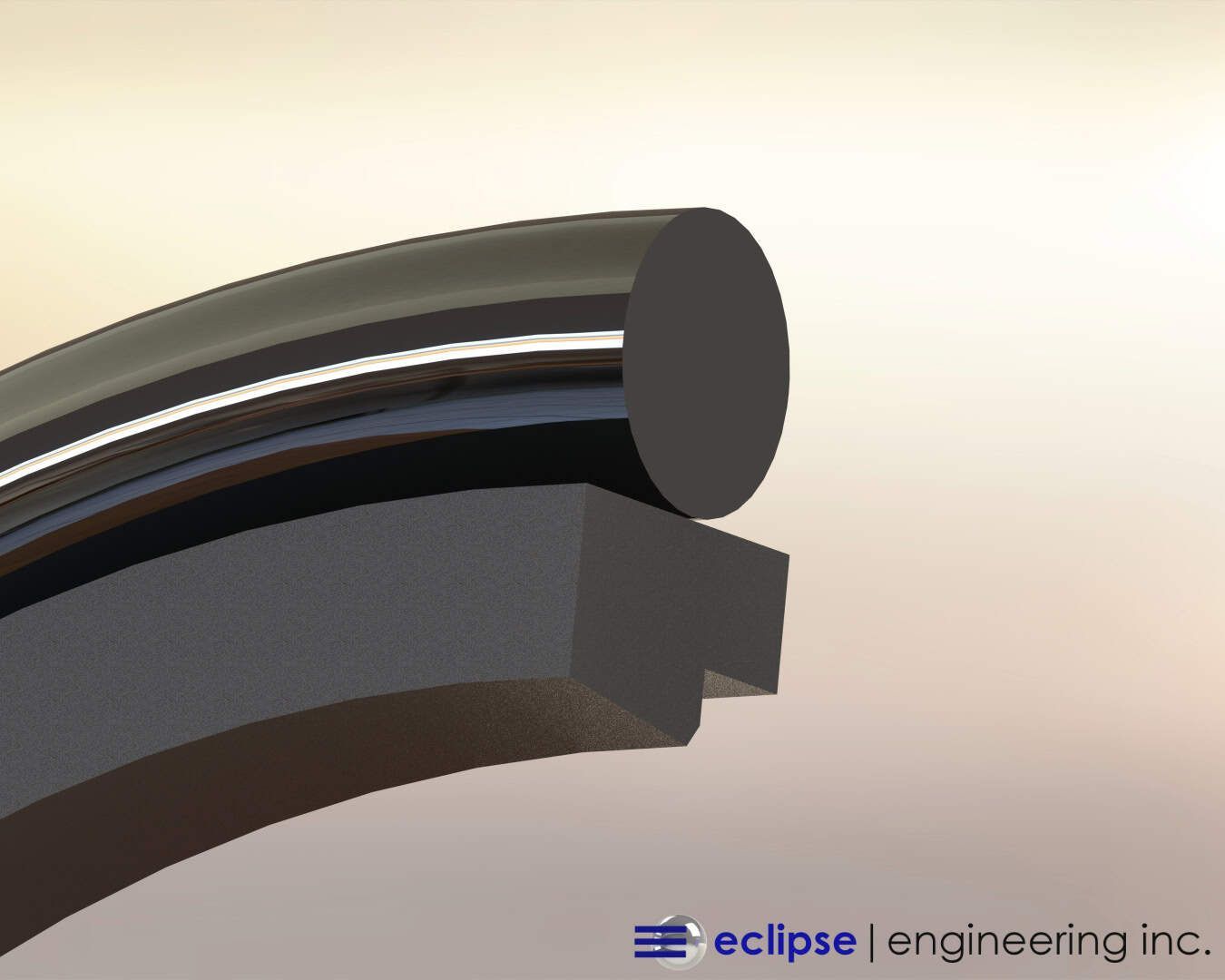
A Teflon® piston seal is a simple cross-section with chamfered edges for installation.
Under pressure, oil can move across the seal interface due to micro-irregularities in the surface finish. With the Buffer Ring, this leakage is not a flaw but a controlled process that helps balance pressure and lubricate the system.
When the rod retracts into the cylinder, the Buffer Ring rocks in its groove.
The back-angle contact side of the seal changes geometry slightly, compressing the trapped oil and pushing it back toward the low-pressure side. This “rocking” or “pivoting” motion effectively pressurizes the oil film and recirculates it into the system — maintaining lubrication while preventing pressure traps.
Some engineers argue that this effect is caused primarily by geometry and surface finish, while others attribute it to the fluid dynamics of pressure equalization. In reality, both mechanisms likely contribute to the Buffer Ring’s unique self-correcting action.
The outcome is clear: less leakage, lower friction, and a longer-lasting seal system than traditional O-ring or U-cup designs.
The History and Ingenuity of the Buffer Ring: Part II
In the 1980s, the Buffer Ring began to gain real traction in the hydraulic sealing market. Customers quickly recognized that the addition of this single component dramatically enhanced overall system performance.
While the manufacturing cost increased slightly, the trade-off was worth it: lower operating temperatures, smoother motion, quieter operation, and most notably, a significant reduction in warranty claims and field failures.
The Buffer Ring proved that a small addition to the rod gland could have an outsized impact on hydraulic cylinder efficiency and longevity.
Buffer rings can also be manufactured as piston seals, though in that configuration, two would be required to operate in both directions. In most cases, a small amount of internal leakage across a Teflon® piston seal is acceptable — since it occurs entirely within the system.
The History of the Buffer Ring
The Buffer Ring originated in Germany and was initially designed to be used with a standard O-ring energizer. But when the design was tested in the United States, engineers made an important discovery: replacing the O-ring with a square ring energizer increased the sealing load by nearly 30%, while also reducing leakage during cylinder extension.
At the time, the gland geometries for the Buffer Ring had already been standardized, so designers simply adapted the configuration — reducing the elastomer width to make room for the new square ring and PTFE sealing element.
This adjustment opened the door to stacked Buffer Ring designs, where two rings could be used without the need for a traditional U-cup.
When paired with a double-acting wiper, leaked oil could be recaptured and returned into the system, creating a more self-contained and efficient hydraulic circuit.
In clean operating environments, these cylinders could even function without an external wiper — though a minor amount of leakage over time was expected.
For construction and heavy equipment applications, however, the addition of a wiper remained standard practice to keep contaminants out.
Back to the Square Ring
A small engineering debate emerged between German and American designers over which energizer type — O-ring or square ring — provided superior performance.
The German design had international recognition, but American engineers favored the square ring for its greater sealing load and stability. In the end, a compromise was reached: increasing the O-ring squeeze achieved better sealability without abandoning the traditional European design.
The decision wasn’t purely technical — square rings weren’t widely available in Europe, and the “not-invented-here” mentality influenced adoption. Still, both versions performed well in the field, and the Buffer Ring continued to evolve as a global sealing solution.
From a designer’s perspective, the square ring remains a strong choice. While over-squeezing an O-ring can shorten its lifespan, these systems always include a secondary sealing element, ensuring redundancy and preventing catastrophic failure.
How Does a Buffer Ring Work?
There are two prevailing schools of thought about how the Buffer Ring functions — and both play a role in its effectiveness.
A Teflon® piston seal is a simple cross-section with chamfered edges for installation.
Under pressure, oil can move across the seal interface due to micro-irregularities in the surface finish. With the Buffer Ring, this leakage is not a flaw but a controlled process that helps balance pressure and lubricate the system.
When the rod retracts into the cylinder, the Buffer Ring rocks in its groove.
The back-angle contact side of the seal changes geometry slightly, compressing the trapped oil and pushing it back toward the low-pressure side. This “rocking” or “pivoting” motion effectively pressurizes the oil film and recirculates it into the system — maintaining lubrication while preventing pressure traps.
Some engineers argue that this effect is caused primarily by geometry and surface finish, while others attribute it to the fluid dynamics of pressure equalization. In reality, both mechanisms likely contribute to the Buffer Ring’s unique self-correcting action.
The outcome is clear: less leakage, lower friction, and a longer-lasting seal system than traditional O-ring or U-cup designs.
The Role of Bushings and Support Elements
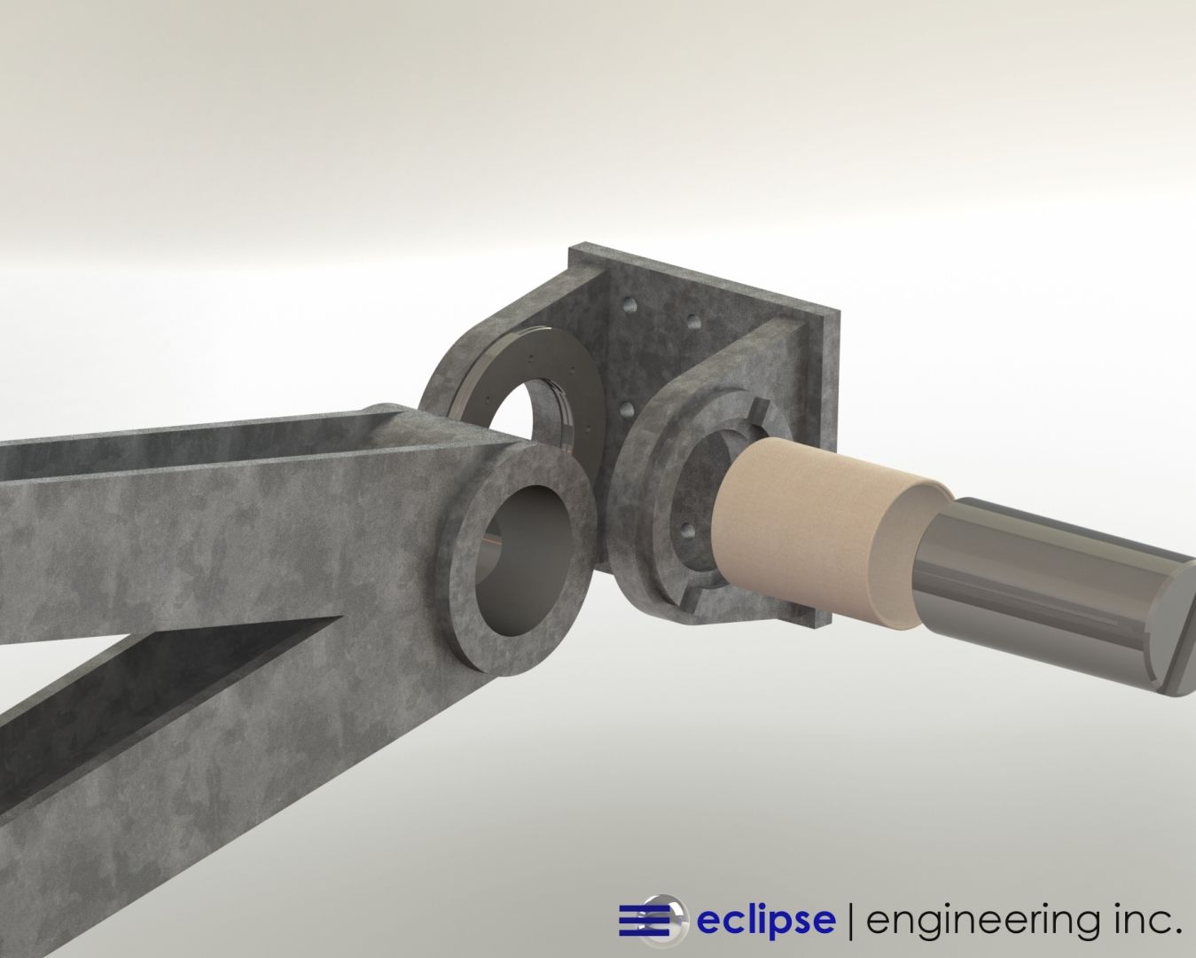
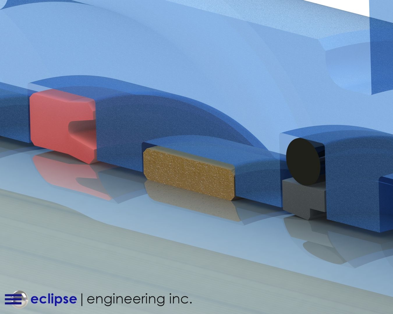
In addition to the Buffer Ring, bushings and wear bands play an essential role in stabilizing the rod and maintaining proper alignment.
Typically, split Teflon® bushings are used on either side of the Buffer Ring assembly — one ahead of the first ring and another between the Buffer Ring and U-cup. This arrangement distributes side-load forces across a wider surface area and keeps the bushings properly lubricated.
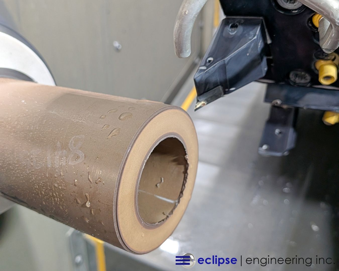
When applications demand higher load-bearing capacity, alternative materials such as filled PTFE composites, PEEK, or thermoplastic bearings can support pressures from 1,000 PSI to over 40,000 PSI compressive.
These advanced materials extend system life in high-pressure, high-cycle environments like aerospace, energy, and heavy-duty hydraulic systems.
Modern Innovations in Buffer Ring Design
Since its introduction, the Buffer Ring has continued to evolve alongside advances in materials science and manufacturing technology.
Today’s designs benefit from precision machining, improved groove geometry, and specialized PTFE blends that outperform earlier versions.
Key Modern Enhancements Include:
- Filled PTFE and polymer composites that resist extrusion and wear.
- Finite Element Analysis (FEA) for optimizing groove geometry and pressure relief.
- Hybrid designs integrating backup rings or anti-extrusion devices for ultra-high pressure.
- Precision micro-machining for consistent dimensions and smoother finishes.
At Eclipse Engineering, our buffer rings are engineered with precision tolerances to meet specific pressure, speed, and temperature requirements.
Every design is backed by decades of hydraulic sealing expertise and advanced testing to ensure reliability in real-world conditions.
Comparing Buffer Rings to Modern Sealing Technologies
While the Buffer Ring remains a cornerstone of hydraulic seal design, it’s important to recognize its place in the broader landscape of sealing solutions.
Compared to U-cups, rod seals, and O-rings, the Buffer Ring is unique because it acts as a pressure modulator rather than a full barrier. It works in tandem with other seals to distribute load, regulate lubrication, and prevent extrusion.
In modern applications, engineers often pair Buffer Rings with custom PTFE seals or O-ring energized profiles, especially in systems where pressure fluctuations, side loads, and extreme temperatures are present.
These combinations provide both sealing integrity and dynamic response under demanding conditions.
Applications of Buffer Rings in Today’s Industries
Buffer Rings have found their way into nearly every industry where hydraulic or pneumatic power is used. Common applications include:
- Heavy Equipment & Construction Machinery – backhoes, loaders, and excavators.
- Agricultural Equipment – hydraulic actuators and control systems.
- Aerospace & Defense – landing gear, actuators, and hydraulic flight systems.
- Industrial Manufacturing – presses, molding systems, and automation cylinders.
- Oil & Gas – drilling and valve actuation systems requiring high-pressure sealing.
Their ability to extend seal life, prevent leaks, and maintain smooth operation makes them indispensable in modern engineering design.
Why Material Science Still Matters
As sealing requirements evolve, so do the materials that make Buffer Rings more durable, flexible, and chemically resistant.
Modern versions use blends of bronze-filled PTFE, carbon-filled PTFE, UHMWPE, and PEEK composites for different operating conditions.
Choosing the correct compound remains one of the most important decisions in any sealing design. Eclipse Engineering’s team evaluates temperature, media compatibility, motion type, and system pressure to select or develop the right formulation for each project.
Partnering with Eclipse Engineering
At Eclipse Engineering, we continue to advance the legacy of the Buffer Ring with custom designs, advanced materials, and precision manufacturing.
Our engineers specialize in developing complete sealing systems — including buffer rings, U-cups, O-rings, and bearings — that meet the toughest performance and environmental demands.
From prototype development to full-scale production, every Eclipse product is manufactured in the USA and backed by a commitment to performance, innovation, and reliability.
Ready to Enhance Your Hydraulic System?