Understanding Process Capability in Plastic Parts and Seal Design
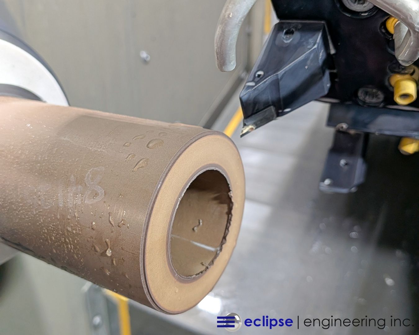
Understanding process capability in plastic parts and seal design starts with recognizing how differently plastics behave compared to metals. Machining plastics is as much a skill as it is an art form, requiring a deep understanding of how materials respond to cutting, stress, and environmental changes.
Whenever a plastic part is machined, it retains some degree of internal energy. Unlike metals, which tend to remain relatively stable after machining, plastics can shift, relax, or deform over time. This is due in part to their higher elasticity and rebound during the cutting process.
While many engineered plastics are considered thermally stable, they are not always dimensionally stable. From the moment a part is machined to when it is installed in an application, temperature fluctuations can cause subtle but meaningful changes in size.
Materials like PTFE (Teflon®) are especially prone to expansion and contraction, even at room temperature, making process capability in plastic machining a critical factor in ensuring consistent seal performance.
What Does “Process-Capable” Really Mean?
In manufacturing, process capability refers to the ability of a machining process to consistently produce parts within specified tolerance limits. It’s a foundational concept in precision plastic machining and custom seal manufacturing, where consistency is just as important as accuracy.
At first glance, it may seem that if a part can be machined and measured within tolerance, then the process is capable. In reality, that assumption often leads to issues, especially with plastic components.
A wide tolerance range does not guarantee process capability. Producing one part that meets specifications does not ensure that the next hundred will. True capability is about repeatability and statistical consistency, not one-off success.
At Eclipse Engineering, process capability is evaluated using real production data. After a machining run, critical dimensions are measured and analyzed to determine variation and standard deviation. This allows us to predict whether future parts are likely to fall within tolerance limits.
This data-driven approach supports the level of quality and consistency customers expect from high-performance sealing solutions and engineered plastic components.
Why Plastic Materials Complicate Process Capability
Achieving process capability in plastic parts is inherently more complex than in metal components. Plastics are more sensitive to environmental and mechanical influences, including:
- Thermal expansion and contraction
- Stress relaxation after machining
- Elastic deformation under load
- Environmental exposure (temperature, humidity, UV)
For example, materials like PEEK offer excellent dimensional stability and can maintain tighter tolerances during machining. In contrast, PTFE is significantly more flexible and prone to movement, making it more difficult to control within narrow tolerance bands.
This is why applying metal-like tolerances to plastic parts often leads to non-capable processes. Plastics simply do not behave the same way during machining or in real-world applications.
Instead, tolerances must reflect both the material properties and the capability of the machining process. This is a core principle behind the design and manufacturing approach used in Eclipse Engineering’s precision sealing solutions.
Designing with Process Capability in Mind
The most effective way to ensure process-capable parts is to consider manufacturing realities during the design phase. This is particularly important in custom seal design, where performance depends on precise interaction between the seal and its mating hardware.
At Eclipse Engineering, standard manufacturing tolerances are based on real-world machining data and material behavior. These tolerances are often broader than those used for metal components, but they are far more realistic for plastic materials.
Tightening tolerances does not necessarily improve performance. In many sealing applications, components operate under pressure and dynamic conditions that cause deformation regardless of how tight the original tolerance is.
Instead, successful designs focus on functional performance within a realistic tolerance range. This ensures that parts perform as intended without introducing unnecessary cost, inspection requirements, or manufacturing challenges.
Critical Dimensions in Seal Performance
Not all dimensions in a seal carry the same level of importance. Understanding which features are critical allows engineers to focus tolerancing efforts where they matter most.
Cross-Section (Wall Thickness)
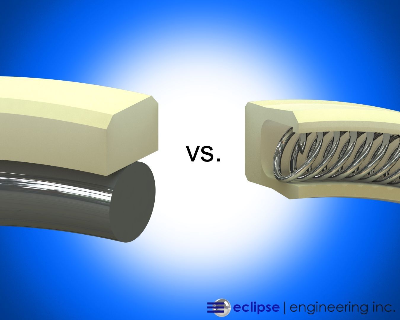
The cross-section is typically the most critical dimension in a sealing application. This measurement directly impacts how the seal is energized, whether by an O-ring or a spring, and how it interacts with the extrusion gap.
If the cross-section is not properly controlled, the seal may fail to generate sufficient sealing force or may extrude under pressure, leading to failure. This is especially important in
spring-energized seals, where precise geometry is essential for performance.
Width
The width of the seal is the second most important dimension. It determines how the seal fits within the gland and whether it can move freely during operation.
A seal that is too tight may bind, while one that is too loose may not maintain proper positioning, both of which can negatively impact performance.
Diameter
Diameter is generally the least critical dimension for sealing performance, but it is still important for proper installation. The seal must fit within the gland without excessive interference.
However, diameter is also the dimension most affected by temperature changes. In larger seals, especially those exceeding a few feet in diameter, tolerances of ±0.060 inches are common. While this may seem large, it reflects the natural expansion and contraction of plastic materials in real-world conditions.
Understanding Process Capability Metrics (Cpk)
To quantify process capability, manufacturers rely on statistical tools such as the Process Capability Index (Cpk). This metric measures how well a process can produce parts within defined tolerance limits.
Cpk accounts for both variation and how centered the process is within the tolerance range. A higher Cpk value indicates a more stable and capable process.
Typical benchmarks include:
- 1.33 Cpk for industrial applications
- 1.67 Cpk for aerospace or critical-use components
A Cpk value below 1.0 generally indicates that the process is not capable and is likely to produce out-of-tolerance parts.
Achieving a high Cpk requires not only tight control, but also designing parts so the process operates within a manageable portion of the tolerance range.
Applying Process Capability in Real-World Manufacturing
In practice, machining processes, tooling, and equipment capabilities are well understood before a part is ever produced. When unrealistic tolerances are specified, it creates unnecessary challenges in production and inspection.
Overly tight tolerances often lead to increased inspection requirements, higher costs, and slower production times, without improving part performance.
A better approach is to:
- Understand the natural capability of the machining process
- Design parts that accommodate expected variation
- Align tolerances with both function and manufacturability
At Eclipse Engineering, process capability data is integrated into both design and quoting. This ensures that parts are not only manufacturable but also reliable in their intended applications.
Customers benefit from this approach through improved performance, reduced risk, and more predictable outcomes across production runs.
Building Reliability into Every Part
Process capability is not just a manufacturing metric—it is a critical factor in long-term seal performance and system reliability.
A part that meets tolerance once is not enough. True reliability comes from a process that consistently produces parts that perform as intended, even as materials respond to temperature, pressure, and time.
By aligning material selection, design strategy, and machining capability, Eclipse Engineering ensures that every component is built with real-world performance in mind.
This commitment to precision and consistency is what defines Eclipse’s approach to custom-engineered sealing solutions across industries and applications.
Learn more about our seal processes and the industries we serve. »